

TL;DR. Spring brake chamber sizing is a three-step decision flow. Step 1 maps vehicle class to chamber size range (9×6 to 30×30). Step 2 matches stroke (44mm to 76mm) to S-cam travel. Step 3 verifies force and response against OE data and ECE R13-H. This article walks through each step with reference chamber models from the Shaoxing Fangjie brake chamber catalog — T9 HF, T12/6200, T18/24, T20, T30/30DD and T30/30DDS — to lock the right chamber from 9×6 to 30×30.
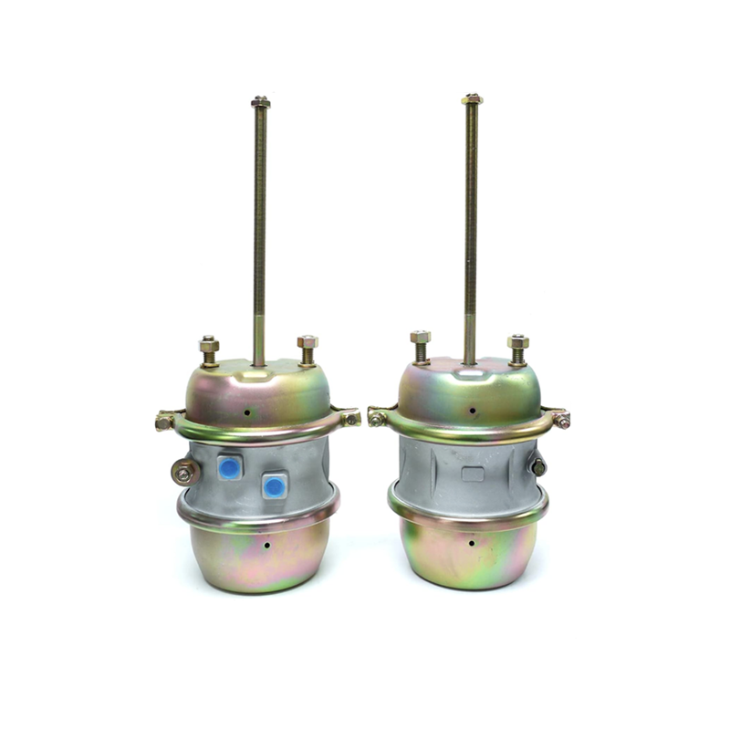
Why Brake Chamber Sizing Is a Decision, Not a Catalog Number
The two-number designation on a spring brake chamber — 9×6, 12×12, 16×16, 20×20, 24×24, 24×30, 30×24, 30×30 — refers to the effective diaphragm area in square inches for the service side and the spring side. The first number is the service-side area; the second is the spring-side area. The stroke number, measured in millimeters, is a separate parameter that has to match the S-cam travel at the axle.
The mistake that recurs in fleet procurement is to pick the chamber by the largest catalog number. A 30×30 chamber is not the universal best choice — it is the right choice for heavy-tractor drive axles with high clamping-force demand and large S-cam travel. The same chamber on a light-trailer rear axle creates three field problems: sluggish response time, excessive push-rod force, and incomplete parking-brake release. The chamber has to match the axle, not the catalog.
The Shaoxing Fangjie brake chamber catalog documents seven of the most common size-and-stroke combinations in production today, with port thread, bolt thread, push rod length and overall length published per model. The three-step flow below uses six of those models as the reference set: T9 HF, T12/6200, T18/24, T20, T30/30DD and T30/30DDS. Together they cover the full 9×6 to 30×30 stroke map for trucks, trailers and buses.
The 3-Step Brake Chamber Stroke Lock Process
The flow below is the same one used by OE brake system engineers when specifying a chamber for a new vehicle program. Step 1 narrows the size range down to two or three candidates based on the axle. Step 2 reduces those candidates to one by matching stroke to mechanical travel. Step 3 verifies that the chosen chamber delivers the clamping force and response time the brake system needs.
The 3-Step Flow: From Vehicle Class to Locked Chamber
Step 1 — Identify Your Vehicle Class and Axle Position
Step 1 is a lookup, not a calculation. Each axle position has a typical chamber size range that has been standardized across the industry.
| Vehicle Class | Axle Position | Chamber Size Range | Reference Model |
|---|---|---|---|
| Light trailer (single-axle, less than 6 tonnes) | Rear axle | 9×6 | T9 HF |
| Medium truck, bus (6 to 12 tonnes) | Front axle | 12×12 / 16×16 | T12/6200 |
| Medium-heavy tractor (12 to 20 tonnes) | Front axle, tag axle | 20×20 / 24×24 | T20 |
| Heavy tractor (20 to 40 tonnes) | Drive axle | 24×30 / 30×30 | T30/30DD |
| Heavy tractor (long-stroke variant) | Drive axle with disc brakes | 30×30 (long-stroke) | T30/30DDS |
Step 2 — Match the Stroke Number to Your Brake System Geometry
Step 2 is where the catalog number is locked. Stroke length determines whether the chamber can physically reach the brake’s full-application point at the axle.
| Chamber Model | Size | Stroke | Push Rod Length | Port Thread |
|---|---|---|---|---|
| T9 HF | 9×6 | 44mm | 123 / 113 / 93mm | 2-M16x1.5 |
| T12/6200 | 12×12 | 48mm | 117 / 124mm | M16x1.5 |
| T18/24 | 18×24 | 64mm | 15.5mm | 2-3/8 inch NPT |
| T20 | 20×20 | 57mm | 200 to 260mm | M16x1.5 / M22x1.5 / 3/8 inch NPT |
| T30/30DD | 30×30 | 64mm | 100 / 115 / 125mm | 3/8 inch NPT |
| T30/30DDS | 30×30 | 64mm / 76mm | 330 / 285 / 340mm | M16x1.5 / 3/8 inch NPT |
The reference rule: the chamber stroke has to be at least as long as the brake’s mechanical-travel requirement at the axle. For drive axles with drum brakes and S-cam geometry, 64mm stroke is the standard. For drive axles with disc brakes, 76mm stroke is increasingly common. The T30/30DDS offers both stroke variants. Port thread selection happens at the same time as stroke selection: European trucks run M16x1.5 or M22x1.5 metric ports; North American trucks run 3/8 inch NPT.
Step 3 — Verify Force Output and Response Time at Locked Stroke
Step 3 is the verification step, and it is the one most often skipped. The catalog documents the chamber, not the brake system performance. The FMCSA and UNECE publish reference brake-system data that buyers can cite.
Three parameters are checked at Step 3:
- Clamping force output at 6.5 bar. A 30×30 chamber generates roughly twice the clamping force of a 9×6 chamber at the same pressure.
- Push rod stroke time. Industry benchmarks for acceptable response time at 6.5 bar supply pressure are between 0.3 and 0.5 seconds.
- Spring-side release pressure (typically 4.5 to 5.5 bar) — a spring side that does not release fully leaves the parking brake partially engaged.
The verification data has to come from the manufacturer’s published test report. The Shaoxing Fangjie spring brake chamber structure guide covers the mechanical principles behind the force and response calculations. For European-market vehicles, UNECE ECE R13-H is the binding regulation that specifies the minimum braking efficiency and the response-time window.
What Happens When the Stroke Map Is Wrong
When the stroke map decision is wrong, the failure shows up in the field, not at the workshop. Three failure modes are common:
- Slow response at low pressure. An undersized chamber (e.g., a 9×6 on a 13-tonne drive axle) generates insufficient clamping force at the standard 6.5 bar supply pressure, lengthening stopping distance.
- Excessive force and accelerated wear. An oversized chamber (e.g., a 30×30 on a light-trailer rear axle) overloads the slack adjuster bushings, the S-cam bushings and the brake lining.
- Spring-side release failure. A mismatched chamber at the high-stroke end (e.g., a 76mm-stroke T30/30DDS on a 48mm-travel brake) may not fully release the parking brake at the system’s air-release pressure. The CVSA inspection programs cite partial parking-brake engagement as a frequent out-of-service violation.
All three failure modes are avoidable by running the three-step flow before placing the chamber order. The catalog number is the output of the flow, not the input.
Brake Chamber Stroke Map Reference Table (9×6 to 30×30)
The reference table consolidates Step 1 and Step 2 into a single lookup. The full catalog covers additional variants (T2424UD, T2430DDLS, T3024, T3030DCP, T3034DCP, T16LCW, T20LCW) for regional niches.
| From (Vehicle) | To (Chamber) | Stroke | Catalog Path |
|---|---|---|---|
| Light-trailer rear axle | T9 HF | 44mm | 9×6 / 2-M16x1.5 / push rod 93-123mm |
| Medium-truck front axle | T12/6200 | 48mm | 12×12 / M16x1.5 / push rod 117-124mm |
| Mid-heavy tractor front axle | T18/24 | 64mm | 18×24 / 2-3/8 inch NPT / push rod 15.5mm |
| Mid-heavy tractor tag axle | T20 | 57mm | 20×20 / multi-port / push rod 200-260mm |
| Heavy-tractor drive axle | T30/30DD | 64mm | 30×30 / 3/8 inch NPT / length 100-125mm |
| Heavy-tractor drive axle (long-stroke) | T30/30DDS | 64mm / 76mm | 30×30 / M16x1.5 or 3/8 inch NPT / push rod 285-340mm |
Frequently Asked Questions
What does the 9×6 to 30×30 stroke range on a spring brake chamber actually mean?
The two-number designation refers to the effective diaphragm area in square inches for the service side and the spring side. A 9×6 chamber (T9 HF, 44mm stroke) is a light-trailer actuator; a 30×30 chamber (T30/30DD, 64mm stroke; or T30/30DDS, 64/76mm stroke) is a heavy-tractor drive-axle actuator. Doubling the area approximately doubles the service force output for the same supply pressure.
Why can’t I just pick the largest chamber (30×30) for every axle?
Oversizing the chamber creates three field problems. First, the response time becomes sluggish because the larger diaphragm volume takes longer to fill at the same air flow rate. Second, the push rod force at the slack adjuster becomes excessive, accelerating wear on the S-cam bushings. Third, the spring-side release pressure rises, which can prevent full parking-brake release. The right chamber matches the axle weight and the brake geometry.
How does port thread choice (M16x1.5 vs 3/8 inch NPT vs M22x1.5) affect chamber selection?
Port thread is a fleet-fitment question, not a performance question. European trucks typically run M16x1.5 or M22x1.5 metric ports. North American trucks typically run 3/8 inch NPT. The T20 documents port thread M16x1.5 / M22x1.5 / 3/8 inch NPT / 2-M22x1.5 / 2-3/8 inch NPT, and the T30/30DDS documents port thread M16x1.5 / 3/8 inch NPT. Adapters on a service-brake circuit introduce a leak risk that no fleet operator will accept.
What stroke length (mm) is appropriate for each chamber size?
Stroke length scales loosely with chamber size but is not a direct function of the two-number designation. Documented stroke values from the catalog: T9 HF is 44mm; T12/6200 is 48mm; T18/24 is 64mm; T20 is 57mm; T30/30DD is 64mm; T30/30DDS offers 64mm or 76mm stroke. A 76mm stroke on a 64mm-travel brake is wasted travel; a 44mm stroke on a 64mm-travel brake cannot reach the mechanical limit of the brake stack.
What is the difference between T30/30DD and T30/30DDS?
Both are 30×30 chambers built for heavy-tractor drive axles, but they target different stroke lengths. The T30/30DD documents 64mm stroke, port 3/8 inch NPT, length 100/115/125mm. The T30/30DDS documents 64mm or 76mm stroke, port M16x1.5 / 3/8 inch NPT, push rod length 330/285/340mm. The T30/30DDS is the long-stroke variant for trucks with greater S-cam travel or for disc-brake calipers that need more linear piston movement.
When does the push rod length (mm) become a selection criterion?
Push rod length becomes a selection criterion at the installation stage, not at the catalog stage. Different chambers document different push rod length ranges: T9 HF at 123/113/93mm; T12/6200 at 117/124mm; T20 at 200-260mm; T30/30DDS at 330/285/340mm. The push rod has to reach the slack adjuster with the right mechanical advantage and without bottoming out at full stroke.
Does the bolt thread (5/8 inch UNC vs M16x1.5 vs M48x2) matter for chamber replacement?
Bolt thread is the mounting-pattern question, and it is the most common reason a chamber swap fails at the workshop. The T9 HF documents M48x2 or 1-3/4 inch-12UN-2A; the T12/6200 documents M48x2; the T18/24 documents 5/8 inch UNC at 120.7mm bolt centre. The bolt thread has to match the mounting studs on the axle bracket. A wrong bolt thread or bolt centre means the chamber cannot be physically bolted to the axle.
Conclusion
The 9×6 to 30×30 stroke map is the same shape across commercial-vehicle OEMs. Step 1 narrows the chamber size by vehicle class and axle position. Step 2 locks the stroke by matching the chamber’s documented stroke value to the brake’s mechanical-travel requirement. Step 3 verifies force output and response time against the OE brake data and ECE R13-H.
The Shaoxing Fangjie brake chamber catalog follows this flow. NHTSA FMVSS 121 and FMCSA provide the regulatory frame: six reference models — T9 HF, T12/6200, T18/24, T20, T30/30DD and T30/30DDS — cover the common size-and-stroke combinations, with documented stroke values, port threads, bolt threads and push rod lengths that map directly onto the Step 1 and Step 2 lookups.
Elian Zhou is the Export Manager at Shaoxing Fangjie Auto Accessory Co., Ltd. (Shaoxing FanDa Import and Export Co., Ltd.), a Shaoxing, Zhejiang-based manufacturer of spring brake chambers, automatic slack adjusters, brake caliper repair kits and ABS solenoid valves for trucks, trailers and buses. Elian coordinates the company’s export business to European, North American and South American fleets and OE customers, with 80% of production exported and long-term relationships in more than 100 countries.
Company: Shaoxing Fangjie Auto Accessory Co., Ltd.
Website: https://www.cnfjautoparts.com/
Post time: Aug-07-2026